|
|
|
|
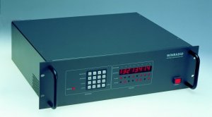
| WA-611 Antenna Distribution System |
|
The WiNRADiO WA-611 Antenna Distribution System features 3 antenna inputs and 6 receiver outputs, and consists of antenna matrix switches,
preamplifiers with an extremely high third order intercept point,
and a combination of suitable filters. Fully integrated to achieve the
best possible performance over a wide frequency range, these systems are eminently
suitable for government, defence, law enforcement and other demanding high-end
applications.
The antenna inputs are configured as follows:
The unit also contains the following user-switchable filters, in addition to the fixed band preselector filters. These are used to reject broadcast frequencies:
|
|
|
|
Front View
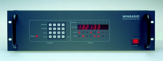
The front panel of the WA-611 unit is divided into a keypad area and the status display. The keypad is used to enter the matrix configuration (which receiver is connected to which antenna), to switch on/off the attenuators and band-stop filters, and to enable/disable remote control.
|
|
|
|
Rear View
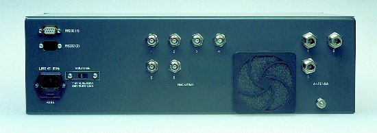
The antennas are connected using N-type connectors at the rear of the unit. The receivers are connected via BNC connectors. Connecting to the RS-232 serial port is done via a standard 9-pin connector. An optional second RS-232 port may be installed by special requirement. (This is usually used in high-reliability redundancy systems where the second RS-232 port is connected to a back-up computer equipment.) |
|
|
|
Remote Operation In remote operation mode, the unit will accept commands from the host computer and continue showing the current settings on the front panel status display. The unit can be controlled and its status interrogated via the serial interface, using a set of ASCII commands. For a detailed explanation of the low-level control commands, click here.
|
|
|
|
Control Software
For easy control of the unit from a PC under Windows, virtual control panel software is available, and supplied as part of the package. This software has a self-explanatory graphical user interface which makes it possible for the operator to observe what is happening inside the unit:
Virtual control panel of WA-611 The status of the antenna matrix is observed in a grid of antenna inputs and receiver outputs, and is easily changed by clicking on the intersecting lines. The status of filters and attenuators is shown by highlighting of the active attenuators or filters, and changed by simply clicking on the corresponding function blocks. Note also that power for the external antenna preamplifiers can be controlled from here, by clicking on the associated power supply blocks. |
|
|
|
Technical Specifications
Active device third order intercept point (typical values)
Dynamic range (typical values)
Power 120/240 VAC, selectable Dimensions
Width: 19" rack Weight 19.5 lb (8.8 kg) Specifications are subject to change without notice. |